Dimension Drawing
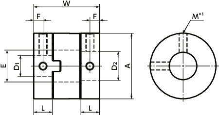
*1: In a case where the bore diameter is φ 4 or less, the set screw is used in only one place.
Specs/CAD
Unit : mm
| Part Number | A | L | W | E | F | M | Screw Tightening Torque (N・m) |
Standard Bore Diameter (Dimensional Allowance Metric Bore:H8, Inch Bore:H7) D1-D2 |
CAD Download |
Cart |
|---|---|---|---|---|---|---|---|---|---|---|
| MOR-6 | 6 | 2.5 | 8.4 | 2.1 | 1.3 | M2 | 0.18 | - | CAD | RFQ |
| MOR-8 | 8 | 2.5 | 9.6 | 3.1 | 1.3 | M2 | 0.18 | - | CAD | RFQ |
| MOR-10 | 10 | 2.9 | 10.4 | 4.1 | 1.4 | M2 | 0.18 | - | CAD | RFQ |
| MOR-12 | 12 | 3.9 | 14.4 | 5.2 | 2 | M3 | 0.7 | - | CAD | RFQ |
| MOR-15 | 15 | 4.4 | 16 | 8.2 | 2.2 | M3 | 0.7 | - | CAD | RFQ |
| MOR-17 | 17 | 4.9 | 19.7 | 8.2 | 2.5 | M3 | 0.7 | - | CAD | RFQ |
| MOR-20 | 20 | 5.8 | 21.6 | 12.2 | 2.9 | M3 | 0.7 | - | CAD | RFQ |
| MOR-26 | 26 | 7.3 | 25.6 | 14.2 | 3.7 | M4 | 1.7 | - | CAD | RFQ |
| MOR-30 | 30 | 10 | 32.6 | 16.2 | 5 | M4 | 1.7 | - | CAD | RFQ |
| MOR-34 | 34 | 11.1 | 34 | 16.2 | 5.6 | M5 | 4 | - | CAD | RFQ |
| MOR-38 | 38 | 12.1 | 40.1 | 20.3 | 6.1 | M5 | 4 | - | CAD | RFQ |
| MOR-45 | 45 | 13.8 | 46 | 22.3 | 6.9 | M6 | 7 | - | CAD | RFQ |
| MOR-55 | 55 | 18.7 | 57 | 26.5 | 9.4 | M8 | 15 | - | CAD | RFQ |
| MOR-68 | 68 | 24 | 77 | 38.5 | 12 | M10 | 30 | - | CAD | RFQ |
| Part Number | Max. Bore Diameter (mm) |
Keyway Additional Modification Max. Bore Diameter (mm) |
Rated Torque*1 (N・m) |
Max. Torque *1(N・m) |
Max. Rotational Frequency (min-1) |
Moment of Inertia (kg・m2)*2 |
Static Torsional Stiffness (N・m/rad) |
Max. Lateral Misalignment (mm) |
Max. Angular Misalignment (°) |
Mass (g) *2 |
|---|---|---|---|---|---|---|---|---|---|---|
| MOR-6 | 2 | - | 0.2 | 0.4 | 100000 | 2.2×10⁻⁹ | 5 | 0.5 | 3 | 0.4 |
| MOR-8 | 3 | - | 0.5 | 1 | 78000 | 7.4×10⁻⁹ | 12 | 0.7 | 3 | 0.8 |
| MOR-10 | 4 | - | 0.8 | 1.6 | 63000 | 1.9×10⁻⁸ | 23 | 0.9 | 3 | 1 |
| MOR-12 | 5 | - | 1 | 2 | 52000 | 5.3×10⁻⁸ | 60 | 1 | 3 | 3 |
| MOR-15 | 8 | 8 | 1.6 | 3.2 | 42000 | 1.4×10⁻⁷ | 80 | 1 | 3 | 4 |
| MOR-17 | 8 | 8 | 2.2 | 4.4 | 37000 | 2.8×10⁻⁷ | 120 | 1.2 | 3 | 7 |
| MOR-20 | 12 | 12 | 3.2 | 6.4 | 31000 | 5.7×10⁻⁷ | 120 | 1.2 | 3 | 9 |
| MOR-26 | 14 | 14 | 6 | 12 | 24000 | 2.1×10⁻⁶ | 300 | 1.5 | 3 | 20 |
| MOR-30 | 16 | 16 | 15 | 30 | 21000 | 5.4×10⁻⁶ | 530 | 2 | 3 | 38 |
| MOR-34 | 16 | 16 | 16 | 32 | 18000 | 9.1×10⁻⁶ | 1000 | 2.5 | 3 | 52 |
| MOR-38 | 20 | 20 | 28 | 56 | 16000 | 1.6×10⁻⁵ | 1500 | 2.5 | 3 | 69 |
| MOR-45 | 22 | 22 | 30 | 60 | 14000 | 3.3×10⁻⁵ | 2400 | 3 | 3 | 110 |
| MOR-55 | 26 | 26 | 45 | 90 | 11000 | 1.0×10⁻⁴ | 4100 | 4 | 3 | 230 |
| MOR-68 | 38 | 38 | 80 | 160 | 9000 | 3.7×10⁻⁴ | 6400 | 4.5 | 3 | 430 |
*1: Values with no load fluctuation and rotation in a single direction. If there is large load fluctuation, or both normal and reverse rotation, select a size with some margin. If ambient temperature exceeds 30°C, be sure to correct the rated torque and max. torque with temperature correction factor shown in the following table. The allowable operating temperature of MOR is -20°C to 80°C.
*2: These are values with max. bore diameter.
Unit : mm
| Part Number | Standard Metric Bore Diameter (dimensional allowance H8) D1・D2 |
||||||||||||||||||||||
|---|---|---|---|---|---|---|---|---|---|---|---|---|---|---|---|---|---|---|---|---|---|---|---|
| 1 | 1.5 | 2 | 3 | 4 | 5 | 6 | 6.35 | 8 | 9.525 | 10 | 12 | 14 | 15 | 16 | 18 | 20 | 22 | 25 | 28 | 30 | 35 | 38 | |
| MOR-6 | ● | ● | ● | ||||||||||||||||||||
| MOR-8 | ● | ● | ● | ||||||||||||||||||||
| MOR-10 | ● | ● | ● | ||||||||||||||||||||
| MOR-12 | ● | ● | ● | ||||||||||||||||||||
| MOR-15 | ● | ● | ● | ● | ● | ||||||||||||||||||
| MOR-17 | ● | ● | ● | ● | ● | ||||||||||||||||||
| MOR-20 | ● | ● | ● | ● | ● | ● | ● | ● | |||||||||||||||
| MOR-26 | ● | ● | ● | ● | ● | ● | ● | ● | |||||||||||||||
| MOR-30 | ● | ● | ● | ● | ● | ● | ● | ||||||||||||||||
| MOR-34 | ● | ● | ● | ● | ● | ||||||||||||||||||
| MOR-38 | ● | ● | ● | ● | ● | ● | ● | ||||||||||||||||
| MOR-45 | ● | ● | ● | ● | ● | ● | ● | ● | |||||||||||||||
| MOR-55 | ● | ● | ● | ● | ● | ● | ● | ||||||||||||||||
| MOR-68 | ● | ● | ● | ● | ● | ● | ● | ● | |||||||||||||||
Unit : inch
| Part Number | Standard Inch Bore Diameter (dimensional allowance H7) D1・D2 |
||||||
|---|---|---|---|---|---|---|---|
| 1/4 | 5/16 | 3/8 | 1/2 | 5/8 | 3/4 | 7/8 | |
| MOR-15 | ● | ● | |||||
| MOR-17 | ● | ● | |||||
| MOR-20 | ● | ● | ● | ||||
| MOR-26 | ● | ● | ● | ● | |||
| MOR-30 | ● | ● | ● | ||||
| MOR-34 | ● | ● | ● | ||||
| MOR-38 | ● | ● | ● | ● | |||
| MOR-45 | ● | ● | ● | ||||
| MOR-55 | ● | ● | ● | ||||
● All products are provided with hex socket head cap screw.
● In a case where the bore diameter is φ 4 or less, the set screw is used in only one place.
● Recommended tolerance for shaft diameters is h6 and h7.
● A set of hubs with set screw type for one side and clamping type for the other side and others are available upon request.
● Bore and keyway modifications are available on request. Please take advantage of our modification services.
●For the shaft insertion amount to the coupling, see Mounting/maintenance. ⇒Mounting and Maintenance
Ambient Temperature / Temperature Correction Factor
| Ambient Temperature | Temperature Correction Factor |
|---|---|
| -20℃ to 30℃ | 1.00 |
| 30℃ to 40℃ | 0.80 |
| 40℃ to 60℃ | 0.70 |
| 60℃ to 80℃ | 0.55 |
Slip torque
For slip torque, see Aluminum Alloy Coupling under "Slip Torque of Coupling - Set Screw Type" for details.Structure
Set Screw Type
MOR MOR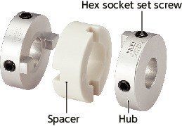
Clamping Type
MOR-C MOR-C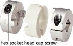
Set Screws + Key Type
MOR-K MOR-K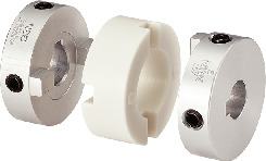
Clamping + Key Type
MOR-CK MOR-CK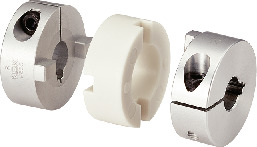
Material/Finish
| MOR | |
|---|---|
| Hub | A2017 Anodized*1 |
| Spacer | Polyacetal |
| Hex Socket Set Screw | SCM435 Ferrosoferric Oxide Film (Black) |
| Hex Socket Head Cap Screw | SCM435 Ferrosoferric Oxide Film (Black) |
*1:Due to manufacturing process requirements, couplings may have bores with or without surface treatment. This does not affect the performance of the couplings.
Characteristics
- Applicable Motor
| MOR | |
|---|---|
| Servomotor | - |
| Stepping Motor | - |
| General-purpose Motor | ◎ |
- Property
| MOR | |
|---|---|
| High Torque | ◎ |
| Allowable Misalignment | ◎ |
| Small Eccentric Reaction Force | ◎ |
| Electrical Insulation | ◎ |
| Allowable Operating Temperature | -20℃ to 80℃ |
- This is an oldham type flexible coupling.
- Slippage of hubs and a spacer allows large eccentricity and angular misalignment to be accepted.
- The eccentric reaction generated by misalignment is small and the burden on the shaft is reduced.
- The simple structure allows the unit to be easily assembled.
Application
Sputtering device / Parts feeder / Industrial sewing machine / Amusement deviceSelection
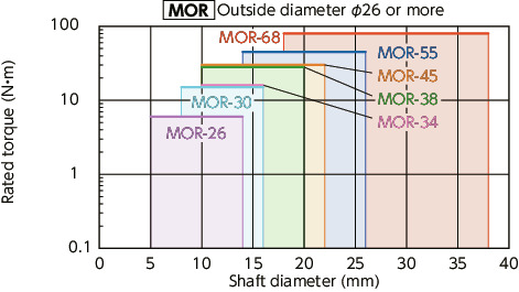
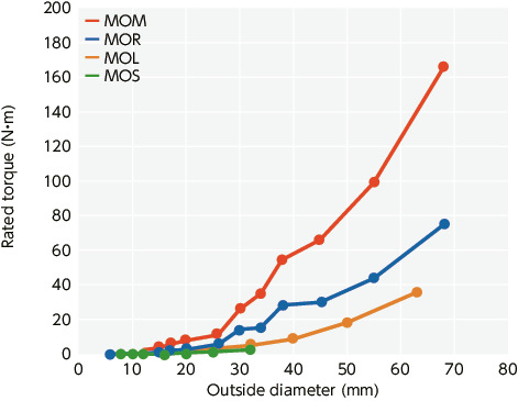
Selection Based on Shaft Diameter and Rated Torque
The area bounded by the shaft diameter and rated torque indicates the selection size.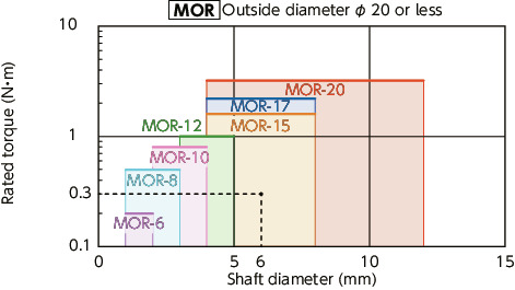
Selection Example
In case of selected parameters of shaft diameter of φ 6 and load torque of 0.3 N•m, the selected size is MOR-15.Comparison of Rated Torque
Chemical resistance of the spacer (Polyacetal)
| Effect | |
|---|---|
| Weather Resistance | Slight Change in Color |
| Weak Acid Resistance | Minor Effect |
| Strong Acid Resistance | Effect |
| Weak Alkali Resistance | Minor Effect |
| Strong Alkali Resistance | Minor Effect |
| Organic Solvent Resistance | Includes Resistance |
Physical property of the spacer (Polyacetal)
| Test Method | unit | Polyacetal | |
|---|---|---|---|
| Density | ISO 1183 | g/cm3 | 1.36 |
| Water Absorption (23°C, Dipped for 24 hr) |
ISO 62 | % | 0.7 |
| Tensile Strength | ISO 527-1, 2 | N/mm2 | 52 |
| Bending Strength | ISO 178 | N/mm2 | 72 |
| Charpy Impact Strength (with Notch) |
ISO 179 / 1eA | kJ/m2 | 5.9 |
| Deflection Temperature Under Load (1.8MPa) |
ISO 75-1, 2 | °C | 85 |
| Insulation Breakdown Strength (3mmt) |
IEC 60243-1 | kV/mm | 20 |
| Volume Resistivity | IEC 60093 | Ω·cm | 1 x 10¹⁴ |
| Combustibility | UL94 | - | HB |
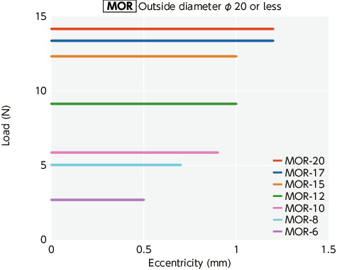
Eccentric Reaction Force
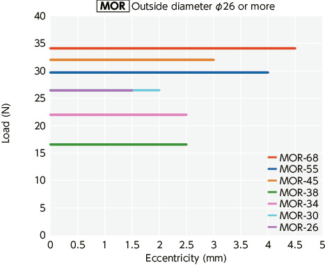
After running-in operation, the slippage load becomes small, the load on the shaft due to misalignment becomes lowered, and the burden on the shaft bearing is reduced.
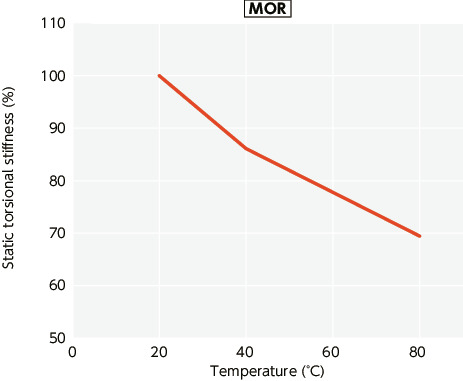
Change in static torsional stiffness due to temperature
This is a value under the condition where the static torsional stiffness at 20°C is 100%.Changes in the static torsion spring constant within the operating temperature are shown in the graph.
Before using the unit, be aware of the deterioration of responsiveness.
Specification Changes
Please be informed of the following changes to the specifications of some sizes of the Flexible Coupling – Set Screw Type.See here for details
https://www.nbk1560.com/news/2025/20251203_Flexible-Coupling/