

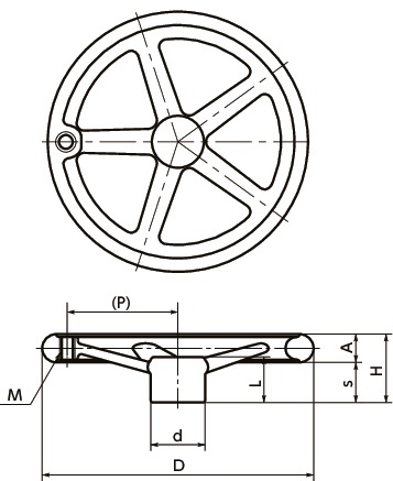
Dimension Drawing
Specs/CAD
Unit : mm
| Part Number | M (Coarse) Nominal of Thread |
Pitch | D | H | A | s | d | L | P | Mass (g) |
Number of Spokes | CAD Download |
Cart |
|---|---|---|---|---|---|---|---|---|---|---|---|---|---|
| D-80 | M5 | 0.8 | 80 | 36 | 14 | 22 | 24 | 24 | 27 | 430 | 3 | CAD | RFQ |
| D-100 | M5 | 0.8 | 100 | 39 | 15 | 24 | 30 | 25 | 35.5 | 630 | 3 | CAD | RFQ |
| D-125 | M6 | 1 | 125 | 40 | 16 | 24 | 33 | 28 | 46.5 | 755 | 3 | CAD | RFQ |
| D-140 | M6 | 1 | 140 | 44 | 17 | 27 | 35 | 30 | 53.5 | 1360 | 3 | CAD | RFQ |
| D-150 | M8 | 1.25 | 150 | 46 | 18 | 28 | 35 | 32 | 56 | 1410 | 3 | CAD | RFQ |
| D-160 | M8 | 1.25 | 160 | 46 | 18 | 28 | 37 | 32 | 61 | 1200 | 3 | CAD | RFQ |
| D-200 | M10 | 1.5 | 200 | 60 | 24 | 36 | 43 | 41 | 77 | 2250 | 3 | CAD | RFQ |
| D-250 | M10 | 1.5 | 250 | 63 | 25 | 38 | 50 | 42 | 101.5 | 3710 | 5 | CAD | RFQ |
| D-300 | M12 | 1.75 | 300 | 66 | 26 | 40 | 56 | 45 | 122 | 6150 | 5 | CAD | RFQ |
| D-315 | M12 | 1.75 | 315 | 72 | 28 | 44 | 60 | 49 | 128.5 | 6650 | 5 | CAD | RFQ |
Material/Finish
| D | |
|---|---|
| Main body | FC200 Chrome Plating |
Characteristics
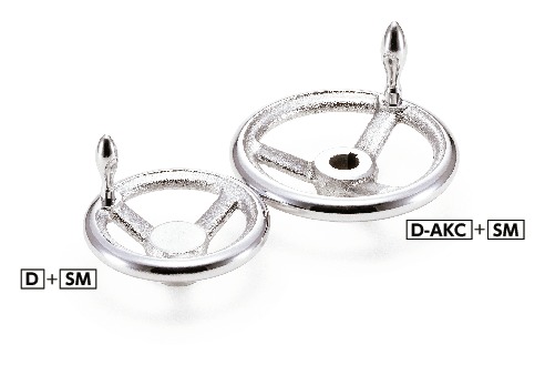
- Products with/without grip mounting holes can be selected by the end symbol of the part number.
D----With grip mounting hole
D-N----Without grip mounting hole - There is no grip supplied with this product. Order a grip separately. ⇒Grips
Recommended applicable grip
| Part Number | Recommended Applicable Grip*1 | |
|---|---|---|
| Plated Revolving GripRM RM |
Plated Fixing GripSM SM |
|
| D-80 | SM-5 | |
| D-100 | SM-5 | |
| D-125 | RM-6 | SM-6 |
| D-140 | RM-6 | SM-6 |
| D-150 | RM-8 | SM-8 |
| D-160 | RM-8 | SM-8 |
| D-200 | RM-10 | SM-10 |
| D-250 | RM-10 | SM-10 |
| D-300 | RM-12 | SM-12 |
| D-315 | RM-12 | SM-12 |
*1: If a revolving grip other than the recommended applicable grip is used, the grip may not rotate.


