Date Published:Jul. 31. 2020
Advancements in Servomotor Coupling Technology
Advancements in Servomotor Coupling Technology
Flexible couplings are machine elements that fasten drive shafts and transmit torque while allowing for multiple forms of misalignment such as lateral, angular, and axial. Various flexible coupling types have been developed based on application demands.
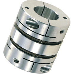
Couplings used in servo systems with specific feedback mechanisms are often selected due to their static torsional stiffness and backlash-free features which are integral requirements for high precision and high-speed applications. Typically, users are accustomed to utilizing the disk coupling with static torsional stiffness capability (Pic.1*).
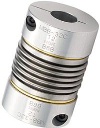
Recent technological improvements in servomotors have led to dramatic improvement in speed response frequency. Vibration (aka “hunting”) occurrence tends to arise as when increased gain settings are applied to servo systems using high static torsional stiffness coupling such as the disk or bellows type (Pic.2**).
A potential solution to resolve hunting while operating servo system at high gain settings involves equipping the coupling with vibration damping technology. Further discussion will analyze the extent of the high-gain rubber type coupling’s features as a solution for high response mandatory servo systems designed for the semiconductor manufacturing equipment as well as many other automation fields.
**Pic. 2 Bellows type
Stabilization Time’s Effect on Productivity
Integrated damping technology has the ability to greatly reduce stabilization time for speed purposes, but increase productivity as whole.
The interplay between a feed screw machine with a ball screw and servomotor system illustrates a potential operation issue. For feed screw related applications which utilize both servomotors and ball screws, the ideal scenario dictates that operation proceeds in exact accordance with the servomotor's commands; however, real life scenarios may experience a situation where executed commands are delayed. Delayed response is a factor in errant positioning, and this delayed response is known as stabilization time (See Fig. 1).
●Fig. 1 Stabilization time

Higher servomotor gain and high-response operation are required for reduced stabilization time (Fig. 2), but substantial gain increases are likely to lead to the counterproductive hunting phenomena. Hunting, in effect, will distort the application’s operating equilibrium and disable servo-motor control. Increasing the gain while suppressing hunting requires systematic adjustments to the servomotor parameters such as reviewing the coupling’s mechanical characteristics.
Tests have shown that when a servomotor contains a disk or bellows couplings that raising the gain tends to cause hunting occurrence much more readily. When hunting occurs, conventional wisdom proposes switching to a coupling with higher torsional stiffness to increase the rigidity of the entire rotating system. However, the torsional rigidity of the entire system is dependent on the torsional rigidity of the ball screw.
●Fig. 2 Change in stabilization time due to gain

Table 1 shows the calculated values of the torsional rigidity of the entire system utilizing different couplings. The torsional rigidity value of the disk coupling is 450 N.m/rad compared to the highgain rubber type coupling value of 240 N.m/rad. Strictly examining the values, one would conclude that the disk coupling has 1.9 times higher torsional stiffness values. Further examination reveals that the torsional rigidity of the entire system with a disk coupling is 79 N.m/rad for the former and 68 N.m/rad for the latter, making the actual difference about 1.2 times. In other words, the torsional rigidity of the ball screw is the greater determining factor for the torsional rigidity of the entire system, not the coupling. Simply changing the coupling with inherent higher torsional stiffness values may not sufficiently improve the torsional rigidity of the entire system nor provide protection against hunting occurrence.
●Table 1 Torsional rigidity of the entire system
| Values (Units) | Disk type | High-gain rubber type |
|---|---|---|
| Torsional rigidity of coupling: Kc (N.m/rad) |
450 | 240 |
| Ball screw groove diameter (mm) |
7.8 | 7.8 |
| Support bearing - Nut distance (mm) | 300 | 300 |
| Torsional rigidity of ball screw: Kbs (N.m/rad) | 96 | 96 |
| Torsional rigidity of entire system*: K (N.m/rad) | 79 | 68 |
Technical advancements in servomotors especially in speed response frequency (Fig. 3) have made the need for increased vibration damping capability even more pronounced to avoid hunting. Ultimately, vibration damping along with adequate statistic torsional stiffness allows for accurate repeat position repeatability to ensure positioning accuracy.
●Fig. 3 Industry changes in servomotor speed response frequency*
(Note: Based on servomotor speed response frequency manufactures’ catalog values)

1.Purpose
2.Testing equipment
| Equipment | Part numbers | Notes |
|---|---|---|
| Actuator | KR30H | Positioningrepeatability:±0.005(mm) |
| Position accuracy:±0.1(mm) | ||
| Motor | HF-KP013 | |
| Couplings |
XGT-25C-6-8 (High-gain rubber type) |
Static Torsional Stiffness: 170(Nm/rad) |
|
XBW-25C2-6-8 (Disk type) |
Static Torsional Stiffness: 850(Nm/rad) | |
|
MJT-20C-RD-6-8 (Jaw Type) |
Static Torsional Stiffness: 55(Nm/rad) | |
| Laser Displacement Sensor | XL-80 |

3. Method
Testing methodology adheres to JIS B 6192 (Japanese Industrial Standards) protocols and the testing equipment used the high-gain rubber type, disk type and jaw type couplings where the accuracy of stop position accuracy was measured 7 times. The gap of Max. and Min. values was calculated and respective values were compared (See test results). The origin of position is set at both the center and edge for the max range liner stroke. Max value as testing parameter was written in ± (plus minus) with its half value as below.4. Testing Conditions
| Motor speed | 3000 [min-1] |
| Acceleration/deceleration time | 50 [ms] |
| Positioning location | 20 [mm], 170 [mm], 350 [mm] |
| Loaded object | 3 [kg] |
5. Testing Results
| Unit |
High-gain rubber type | Disk type | Jaw type | |||||||
|---|---|---|---|---|---|---|---|---|---|---|
| Positioning location |
[mm] |
20 | 170 | 350 | 20 | 170 | 350 | 20 | 170 | 350 |
| 1st | [mm] |
19.9983 | 170.0387 | 350.0446 | 19.9989 | 170.0382 | 350.0413 | 20 | 170.358 | 350.0456 |
| 2nd | [mm] |
19.9983 |
170.0394 | 350.0456 | 19.9988 | 170.0387 | 350.042 | 20 | 170.363 | 350.0459 |
| 3rd | [mm] |
19.9983 |
170.0385 | 350.0456 | 19.9987 | 170.0375 | 350.0436 | 20 | 170.366 | 350.0459 |
| 4th | [mm] |
19.9983 |
170.0391 | 350.0452 | 19.9988 | 170.0371 | 350.0433 | 20 | 170.357 | 350.0475 |
| 5th | [mm] |
19.9983 |
170.0396 | 350.0439 | 19.9989 | 170.0376 | 350.0433 | 20 | 170.356 | 350.0466 |
| 6th | [mm] |
19.9984 |
170.0387 | 350.0449 | 19.9989 | 170.0371 | 350.0432 | 20 | 170.359 | 350.0474 |
| 7th | [mm] |
19.9983 |
170.0394 | 350.0469 | 19.9988 | 170.0367 | 350.0426 | 20 | 170.368 | 350.0481 |
| Max. | [mm] |
19.9984 |
170.0396 | 350.0469 | 19.9989 | 170.0387 | 350.0436 | 20 | 170.368 | 350.0481 |
| Min. | [mm] |
19.9983 |
170.0385 | 350.0439 | 19.9987 | 1703071 | 350.0413 | 20 | 170.356 | 350.0456 |
| Gap | [mm] |
1E-04 | 0.0011 | 0.003 | 0.0002 | 0.0016 | 0.0023 | 7E-04 | 0.0012 | 0.0025 |
| Positioning repeatability | [mm] |
0.0015 | 0.0012 | 0.0012 | ||||||
6. Conclusion
Static Torsional Stiffness does not gravely impact positioning repeatability on actuators.Sub-micron value variations referenced above are likely due to the precision performance of the actuator.
High-Gain Rubber Coupling’s Unique Construction
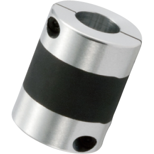
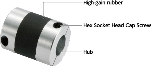
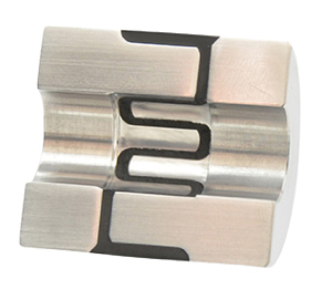
The high-gain rubber type coupling has a completely integrated structure in which aluminum hubs on both sides are molded with a vibration-reduction rubber that prevents backlash yet remains flexible. As seen in picture and figure 4, the internal claw-like structure lined with rubber allows for optimal torsional rigidity and damping.
●Pic.4 Structure of high-gain rubber type
●Fig. 4 Coupling damping performance comparison

The Bode plot (Fig. 5) brilliantly illustrates why the high-gain rubber type coupling has the advantage for increased servomotor gain well beyond the capacity of the disk coupling with higher torsional stiffness values. Gain width between 0 dB and the point where there is a phase delay in the Bode plot is -180° and this is known as the gain margin. General guidelines for servo systems stipulate for setting the gain margin between 10 and 20 dB. As the servomotor gain is increased, the gain margin decreases. When the gain margin falls below 10 dB, hunting tends to occur.
Comparing the limit gain (servo gain at which hunting occurs) of the disk type to the gain margin of the high-gain rubber type, the high gain rubber type at 17.40 dB surpasses the disk type's 9.90 dB value. Since the gain margin is above 10 dB, the servomotor gain of the high-gain rubber type can be increased beyond that of the disk type thus reducing the stabilization time to allow for increased productivity.
●Fig. 5 Bode plot

●Table 2 Difference in stabilization time according to coupling type and servomotor gain
| Servomotor gain* | Disk type | High-gain rubber type |
|---|---|---|
| 25 | 12ms | 12 ms |
| 32 | Occurrence of hunting | 3 ms |
Rubber Durability
Rubber is used as a component to impart damping properties and data on the durability has been accumulated since the advent of high-gain couplings in 2007.
Fig. 6 shows that even after 100 million drive tests, there is no drop in performance due to rubber deterioration.
●Fig. 6 Results of 100 million drive tests

Future Issues
Servomotors are expected to display even higher frequency response in the future paired with demands for higher precision and higher speed. Couplings technology will continue to require a meld of high torsional rigidity and high-level damping properties to help maintain peek servo system performance.Recommended product
High-Gain Rubber Couplings XGT2

Flexible Couplings - High-Rigidity Vibration-Damping Disc Type XGHW

